Introduction: Why Engineers Dread Register Management
In complex digital systems, especially in SoC and FPGA development, consistency between hardware and software definitions is king. Yet, one critical area consistently causes headaches across design, verification, and software teams: managing Control and Status Registers (CSRs).
Manually defining and updating register maps is a slow process prone to error. If the hardware team changes a bit field, the software header files, verification models, and documentation get outdated, and the slow task to manually update them starts again . This tedious, time-consuming replication often results in incompatible register views and wasted effort.
This guide explores a solution to this challenge: adopting a unified workflow centered on the open-source PeakRDL toolchain. By using PeakRDL and the industry-standard SystemRDL language, you can establish a single source of truth for your registers, eliminate inconsistencies, and instantly automate the generation of necessary outputs for every team.
Part 1: The Role of Control and Status Registers (CSRs)
What Are CSRs?
Control and Status Registers (CSRs) are memory-mapped peripherals that typically reside within an SoC, FPGA, or ASIC design. Their primary function is to serve as the interface between hardware and software. They formalize the “contract” between these two domains.
CSRs enable several critical functions within a digital system:
• Operation and Control: They provide a mechanism to control the underlying digital logic.
• Configuration: They allow developers to configure peripherals (e.g., setting the operating mode of an ADC).
• Status Reporting: They expose the results of hardware operations, allowing monitoring of how a peripheral is behaving (e.g., reading a status bit to see if an alarm has tripped).
The Challenge of Multiple Register Views
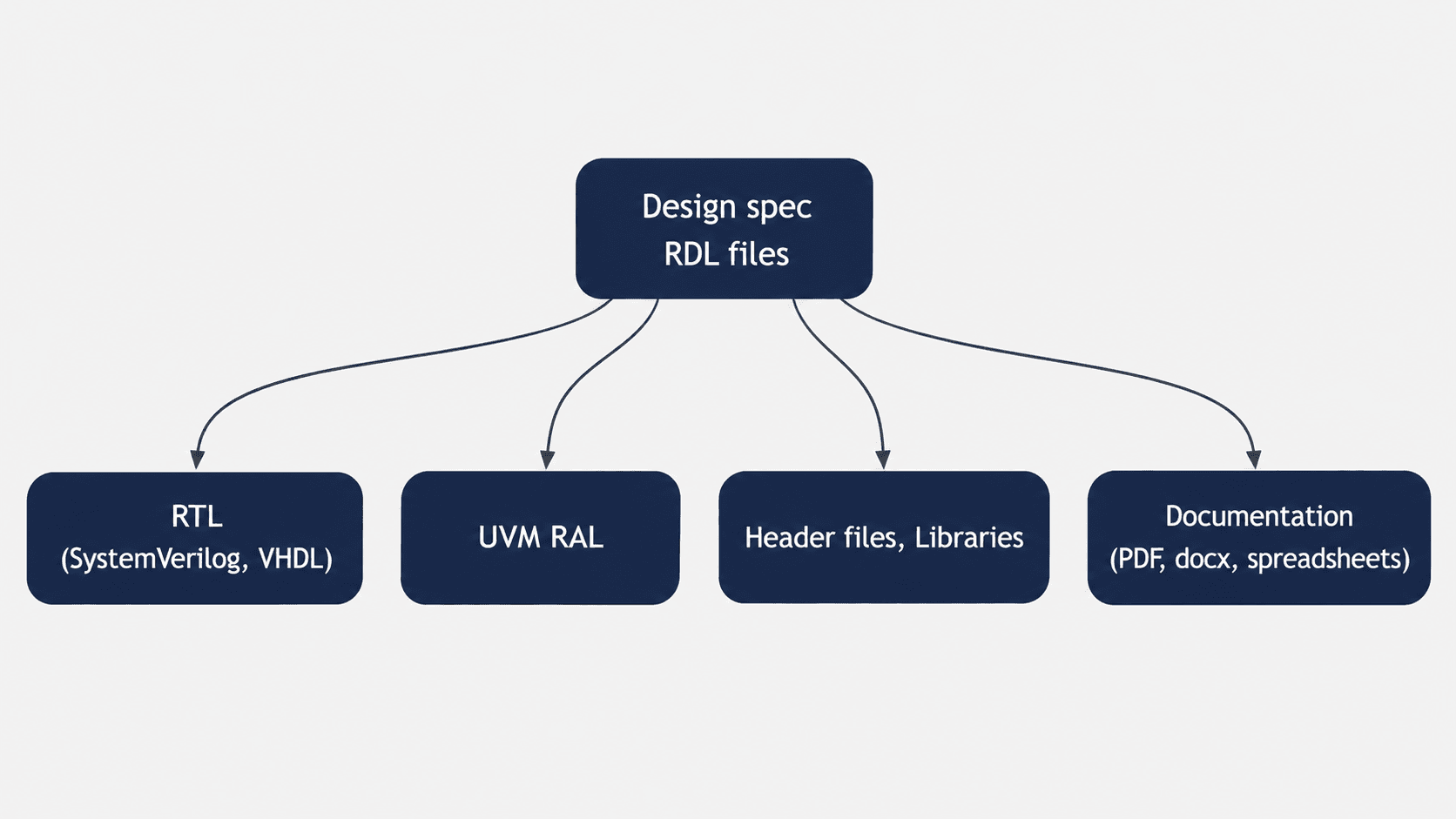
In any digital design project, various teams need to interact with the registers, but they each require the register definitions represented in their own specialized format or “flavor”:
- Digital Design (RTL): Needs synthesizable RTL implementation (SystemVerilog or VHDL) of the register banks.
- Verification Team: Needs the UVM Register Access Layer (RAL) model to develop verification agents and operate tests over the registers.
- Software/Firmware Team: Needs header files (C/C++), structs, and register definitions to access and control the system via memory-mapped buses.
- Documentation/Maintenance: Needs well-written, unified documentation (PDF, HTML, DOCX) for in-house usage or client delivery.
The lack of standardization means maintaining consistency across these diverse outputs is extremely difficult. This necessity for standardization and automation is precisely where PeakRDL provides massive value.
Part 2: Unified CSRs Workflow with PeakRDL
PeakRDL is an open-source CSR toolchain built on Python, designed to automate the process of generating all necessary register views from a single source specification.
The Standardized Specification: SystemRDL
To avoid proprietary or in-house solutions (like using spreadsheets, YAML, or XML), PeakRDL relies on SystemRDL 2.0 (Register Description Language).
SystemRDL establishes the formal specification (the single source of truth) for register definitions. This language provides rich features that go beyond simple data definition:
• Hierarchy and Modularity: You can define reusable block-level registers and parameterized modules that can be instantiated multiple times with different configurations.
• Behavioral Modeling: SystemRDL allows you to describe complex register behavior, such as specific access attributes (e.g., read-only, write-once, default values, fields that clear on read, counters, interrupt logic and more).
• Unification: The language incorporates descriptive properties (name, desc) directly within the register definition, meaning the documentation is built in the same place as the specification.
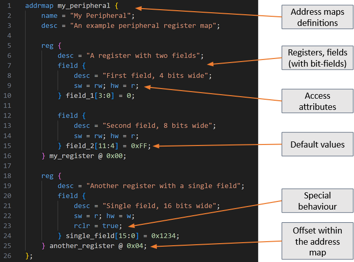
Figure 1: Register definition example of a register map named “my_preipheral”
As can be seen in figure 2, on the top level address map you define the offset each instance will have on the RTL design. You can do it by setting their offsets by hand or, since we will have several instances of the same register map, you can define an array.
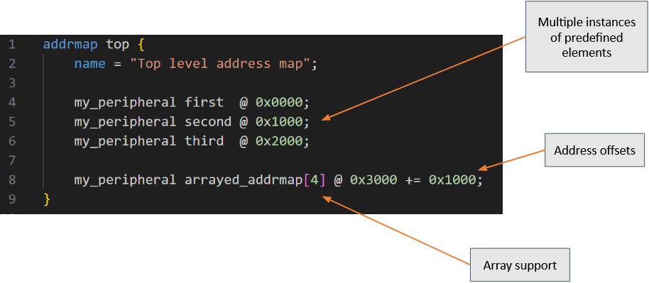
Figure 2: Defining multiple instances of “my_peripheral” register map.
On Figure 3, an example is seen of how to create a parametrized register map and how to instantiate it. Pay special attention to how you can, at the moment of instantiating the peripheral, specify in this example how many channels your device will have.
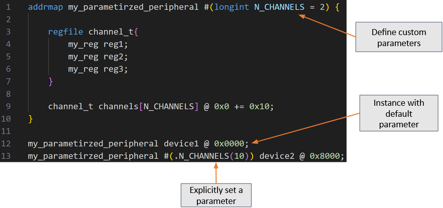
Figure 3: defining a parametrized .
The PeakRDL Automation Engine
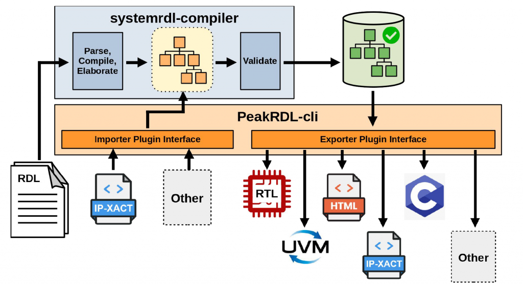
Figure 4: PeakRDL architecture and flow.
The PeakRDL toolchain processes the SystemRDL files a group of components (compiler, importers and exporters), driven by a plug-in centric architecture:
1. Compilation and Validation
The systemrdl-compiler performs the crucial task of parsing, compiling, and elaborating the RDL files, constructing the system hierarchy.
Crucially, this phase includes a validation step to ensure the defined register structure is correct. For instance, the compiler verifies that there are no multiple registers defined in the same address location, catching errors early that might otherwise propagate downstream.
2. The Plugin Interface: Generating Outputs
Once validated, the register definition is ready for export. PeakRDL provides a command-line interface that uses specialized exporters (plugins) to generate team-specific outputs.
There is also a plugin interface for importing register definitions in different formats other than SystemRDL.
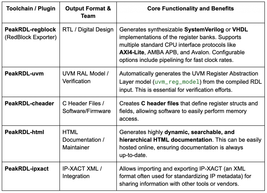
Here is a look at the essential built-in and community plugins and the design roles they support:
How To Use PeakRDL
Using PeakRDL is achieved via the command-line interface. Assuming you have defined your register map in a SystemRDL file (e.g., my_peripheral.rdl), generating outputs is straightforward:
1. Generating Synthesizable RTL (SystemVerilog)
You can specify the register map and the desired CPU bus interface (e.g., AXI4-Lite) using the regblock utility:

This command generates the necessary SystemVerilog files implementing the register logic and the AXI4-Lite interface, instantly providing the Digital Design team with ready-to-use RTL.
2. Generating the UVM Register Model
For the verification team, generating the UVM RAL model is a single command using the uvm plugin:

This output can be exported as a SystemVerilog package or an includable header, depending on the verification environment needs.
3. Generating Dynamic Documentation
To create the documentation required by project maintainers or clients, the HTML plugin is used:

This generates a set of static files representing the documentation.
Real-World Use Cases and Extensibility
The true power of PeakRDL comes from its integration capabilities and extensibility, ensuring the tool works even for highly specialized projects.
Custom Outputs
When a built-in plugin does not meet project requirements, the plug-in centric architecture makes it relatively easy to create custom importers and exporters. We, at Emtech, have developed tailored exporters for our FPGA and microprocessor (SoC) based projects allowing us to create, for example::
• C++ headers for software integration.
• Linux Device Tree entries for system architecture definitions and kernel drivers configuration.
• Tcl scripts for system definition tools like Altera Platform Designer (Qsys project scripts).
Continuous Synchronization via CI/CD
To ensure the single source of truth remains consistent across all teams, PeakRDL can be also integrated into automated build flows and CI/CD pipelines.
When the RTL team updates the base SystemRDL definition and commits the change, the CI/CD pipeline runs the PeakRDL toolchain automatically. This automatically regenerates the updated RTL implementation, the new UVM RAL model, and the latest C/C++ headers.
If the register update causes a conflict (e.g., a bit field name changes) that affects software or verification code, the subsequent automated build processes (that runs on our CI/CD infrastructure) will fail immediately. This signals dependent teams that they must update their code using the newly generated files, enforcing strict synchronization. This synchronization can also be used to automatically generate documentation and host it online (e.g., GitLab pages).
Conclusion: Amplify Your Design Workflow
Using SystemRDL as your single source of truth and leveraging the PeakRDL toolchain, you can automate the painful synchronization process that previously burdened digital design, verification, and software teams.
Don’t aim for perfect manual replication; aim for automatic consistency. Start experimenting with PeakRDL today, and you’ll find that the time saved maintaining registers can be reinvested in focusing on your actual design challenges.
Written by Santiago Abbate
Contact us: info@emtech.com.ar